You are here:   Home  > Motorola > M series > Customisation > Procedure > Sim connector 


The easiest way to connect the SIMemulator to the phone is to use test clips. Disadvantage of these clips are:

  • Every time you want to program the phone you must put on the clips individually, with the change you do not connect the simemulator correctly resulting blowing either the phone or simemulator.
  • Also, since the M-series procedure is quite complicated, some of the clips can snap loose, something that is not very healthy for your phone while transferring.

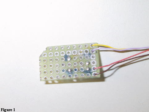
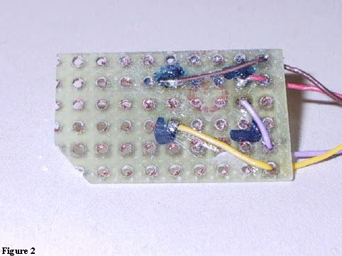
Therefore it is better to use a better construction, an example can be found on this page.

Figure 1 shows how a sim connector can be constructed. What you need is:

  1. General purpose PCB with 1/10” holes and through metalized
  2. Wire wrap cable

Follow the following steps

  1. place your SIM on the PCB in such a way that the contacts of the SIM are located exactly above the holes of the PCB
  2. use a marker to draw the outline of the SIM
  3. Cut or saw the piece out of PCB
  4. File off the back side (i.e. the side that does not make contact to the SIM connector pins of the M3x88), to make it as thin as a SIM.
  5. Solder the wire wrap cables to the corresponding holes (see figure 2).
  6. Pull the wires through the empty holes (and therefore will not break off the PCB) closest to the edge (this way it will fit better in the Phone)
  7. Put some glue on the PCB for extra tightening.


[Alcatel] [Bosch] [Ericsson] [Motorola] [Nokia] [Panasonic] [Philips] [Sagem] [Siemens] [Sony] [Base stations] [Extras] [Miscellaneous]

Page last updated: 21/10/02  


Hosted by uCoz